 |
| March 20, 2012 | Volume 08 Issue 11 |
Designfax weekly eMagazine

Archives
Partners
Manufacturing Center
Product Spotlight
Modern Applications News
Metalworking Ideas For
Today's Job Shops
Tooling and Production
Strategies for large
metalworking plants
Wheels:
Ford accelerates design for manufacturability of conical joints using Abaqus for CATIA and Isight
Developing high-quality bolted joints is an integral part of vehicle chassis design. While less understood than the design of connecting members, such as a toe-link that connects the sub frame to the knuckle, robust joints are critical to improving handling and longevity of vehicle performance. Joints that are loose tend to exacerbate quality issues such as alignment, and ultimately the durability of the joined components. A properly designed joint is more efficient and can support larger loads with smaller size fasteners without loosening.
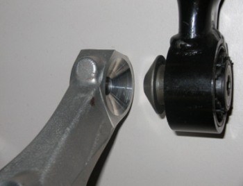
Figure 1: Close-up view of knuckle cone seat and inner-sleeve.
Engineers at Ford Motor Company were tasked to deliver a robust cantilevered conical joint design for the rear suspension system of a midsize passenger car [Figure 1]. To minimize time and cost while meeting functional targets, the team developed an automated Design of Experiments (DOE) process using Abaqus for CATIA (AFC) for structural analysis and Isight for process automation and optimization, both from the SIMULIA brand of Dassault Systèmes.
"Our team chose AFC in order to deploy standard stress modeling and simulation practices in the form of templates to a broader group of engineers within the design organization," says Satyendra Savanur, chassis CAE engineer at Ford Motor Company. "Linking Isight with AFC enabled us to develop a powerful and automated design analysis methodology. We used response surface model, one of the approximation models, for finding optimal parameters to size the joint."
Analyzing conical joint performance
A bolted joint is the most common type of attachment method used in the suspension of a car. In this application, a conical joint is used for connecting the toe-link to the rear knuckle with a cantilevered-type connection. The two mating parts of the conical joint the bushing inner sleeve and the knuckle each have unique manufacturing tolerances of the cone angle.
To develop a robust conical joint between a steel inner sleeve and an aluminum knuckle, the following aspects were considered:
- Manufacturing tolerances of each component;
- Contact area between the cone and seat;
- Angle of the cone; and
- Torque loss after the service load is removed.
To perform virtual tests of their design, the Ford engineers used AFC to create the finite element model of the knuckle and the bushing inner sleeve with the geometry input and material properties from their model created in CATIA, also from Dassault Systèmes. AFC maintains associativity with the CATIA model to ensure that the Abaqus model updates are robust when the CAD model is changed within the usable range of design variables.
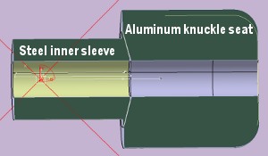
Figure 2: Section of the conical joint.
During the physical assembly process, a forged steel inner cone is forced against an aluminum knuckle seat [Figure 2]. Due to the different manufacturing processes used to make each part, the angular tolerances of the conical design features are different on the inner sleeve and the knuckle mating surface.
"Because of the potential angular mismatch, there are variations in contact area when the two surfaces mate together and the joint is fully torqued," says Savanur. Local yielding can occur in the mating materials, leading to changes in contact area and pressure distribution during assembly of the joint. When the service load is applied, further changes to contact area and contact pressure can occur.
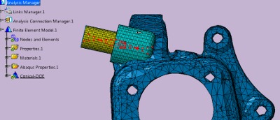
Figure 3: Detailed CAE model. The CAE model shown here was created inside AFC, which has association with CAD data, created in CATIA. This model has three distinct parts: 1. Bushing inner sleeve (yellow) made of steel; 2. Knuckle seat (light blue) made of aluminum; and 3. The knuckle body (dark blue) made of aluminum.
"It is therefore important to simulate both the joint assembly and the loading and unloading, of service loads on the joint during the analysis," explains Savanur. "Our objective was to deliver a robust conical joint design for the entire range of conical mismatch between the cone and the knuckle."
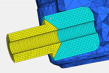
Figure 4: CAE mesh details of the conical joint.
For a robust contact analysis and even contact pressure distribution, the mesh of the inner sleeve was constructed to align with the mesh of the knuckle seat. To facilitate mesh alignment in the contact area, a separate "domain" of the knuckle seat, shown in light blue in Figure 4, was created to simplify meshing. This part was connected to the rest of the knuckle body with a tied contact in Abaqus.
To simulate the bolt assembly process, a virtual bolt between the inner sleeve and the knuckle joint seat was created. External service loads were applied on the sleeve center. Non-linear stress-strain curves for aluminum and steel were imported into AFC to facilitate the nonlinear analysis. Contact pairs and bolt tension were all created inside AFC. Output of contact area (CAREA) and contact force magnitude (CFNM) is possible using AFC for post-processing. Finally, the Abaqus analysis file is output and submitted to the high-performance computing (HPC) cluster for running the analyses.
Managing the DOE process
Ford Motor Company's need to evaluate a large number of designs with different combinations of parameters prompted the engineers to create an automated DOE process. In this process, CAD geometry updates and FEA model updates are completed in the same loop, thus allowing a completely automated DOE approach.
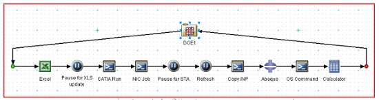
Figure 5: Integrated DOE automation loop using Isight.
At Ford, CATIA startup is customized with an external product management system. Scripting is used to strip away the linkages to the product management system before initializing the CATIA interface.
Design parameters are then fed into CATIA with an external Excel file; a common method used to update a design table within CATIA. The input parameters from the Excel file are mapped to the DOE task of the Isight manager. This enables automatic updates of the Excel sheet for each loop. Since Excel is synchronized with the design table, this results in automatic updates of the CAD geometry inside CATIA. Within AFC, geometry and FE mesh are associated, so the resulting mesh is updated to the changed CAD data.
"By developing a single integrated process, we were able to drive automatic updates of the geometry and mesh at the same time," says Savanur. To manage and control the DOE process, Isight was used as the process automation manager. The resulting automation loop is completely integrated to run CATIA and AFC for CAD updates, creating the Abaqus FE models, and job submission for analysis and post-process results.
The Abaqus component inside the Isight loop was used to extract outputs, including CAREA and CFNM for each run of the DOE. The input parameters from the Excel file are then mapped to these output parameters to create the Isight approximation model.
"In our case, we used the response surface model method of approximation," says Savanur, as seen in Figure 6. This approximate model of conical joint behavior can then be used to show how input affects output and to quickly optimize the conical joint.
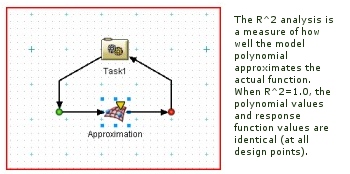
Figure 6: Response Surface Model Method: RSM approximation based on a polynomial fit via the least squares regression of the output parameters to the input parameters.
"This is the first application of an integrated DOE automation loop to morph geometry using CATIA with Abaqus at Ford," says Savanur.
Isight enables more efficient processes
The set-up and validation of the CATIA and AFC scripts, HPC job submission batch file, and the Windows batch command file took time and resources to develop, but were well worth it as they are re-usable for subsequent projects with minor changes.
"Developing a comparable CATIA model with an associated Excel design table, and linked to an associated AFC model, would take approximately three days to construct," says Savanur. "Modifying and debugging the previously developed scripts to run with these new models would take another day. Using Isight, it took about 3.5 hours for the process to complete 35 analysis runs."
"Typically, the manual CAE process consumes two days just to complete one run. Of course, this timing can be reduced if the project is critical, but this is the typical day-to-day turn-around time balancing several projects per engineer," says Joe Peters, chassis CAE supervisor at Ford Motor Company.
Time inefficiencies typically occur in the transfer of data back and forth between CAE and CAD organizations, as people have multiple assignments and do not immediately stop their current work when new design iterations are requested; this is analogous to CPU time verses wall clock time.
"It is estimated it would have taken approximately 70 days to complete all 35 runs, while maintaining other day-to-day work; whereas, our new process eliminates the inefficiencies that were part of the manual CAD/CAE procedures," says Savanur. "By setting up the integrated closed-loop automated DOE loop using Isight, we achieved this task in about four days. This was the only way to help achieve the program objectives of cost and timing with a lean CAE organization.
"Using the automated DOE process, we were able to drastically cut down the time required to develop a robust conical joint with minimal resources," says Peters. "The largest amount of time savings was realized in the automated process of creating a CAE model from CAD. This is a testament to the fact that a small CAE team using new innovative technology helped Ford Motor Company to achieve program objectives."
By using AFC and creating an integrated closed-loop DOE process with the help of Isight, Ford Motor Company was able to deliver a robust conical joint design. This joint exhibits good contact area and retains clamp load after load removal, within the specified manufacturing tolerances.
This case study was developed with the assistance of the following members of the engineering team at Ford Motor Company: Satyendra Savanur, Elaine Hoffman, Rajesh Rajput, Xiaoming Liu, Joe Peters, and Kyu Sohn.
Click to get more information on Abaqus for CATIA (AFC) for structural analysis or Isight for process automation and optimization, both from the SIMULIA brand of Dassault Systèmes
Published March 2012
Rate this article
View our terms of use and privacy policy